Scooping Grasping with Robotic Hand(Reinforcement Learning)

Sungkyunkwan University

Abstract

Learning grasping and lifting through interaction in simulation. Explore the policy rollouts and the hand models that support transfer to a real AIDIN robotic hand.
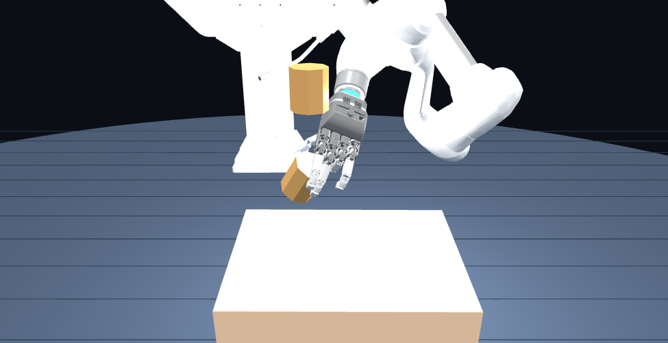
Recorded simulation of the AIDIN hand interacting with an octagonal prism, 100k checkpoint, env4, frame 231
Simulation preview — AIDIN × M0609 · Policy evaluation
100k · Octagonal prism / env4
131observations
21actions · 6 arm + 15 hand
4object families
24saved simulation rollouts

Training and robot execution.

Bring robot geometry and contact conditions into training. Connect object estimates and joint feedback to the policy.

SIMULATION / TRAINING
ENVIRONMENT

Isaac Sim

AIDIN model · Contact pads
Measured table · 20 mm spacer

→
OPTIMIZATION

Reinforcement learning

Object, hand and goal observations
Grasp, lift and sustained support rewards

→
CHECKPOINT

Policy + training config

Preserved checkpoints
Rollout evaluation under matching conditions

↓ 131 observations / 21 actions · Robot profile and normalization
REAL WORLD / EXECUTION
PERCEPTION + STATE

Build observations

D455 · SAM3 · FoundationPose
Object pose + Robot joint feedback

→
INFERENCE

Policy inference

Relative object and goal observations
60 Hz execution configuration

→
CONTROL + FEEDBACK

M0609 + AIDIN

ROS bridge · Target limits
6 arm + 15 hand joints → Joint feedback

Initial hardware execution used the ep50k policy. The ep100k results below are simulation recordings. Deploying the latest policy and measuring repeated hardware success remain future work.

02 / SIMULATION POLICY ROLLOUTS

Four object families.
Replay the learned behavior.

4 families · 8 training assets total 80k / 90k / 100k × 2 environments per family 24 saved rollouts · 600 steps each

Open in new tab ↗

These saved trajectories are comparisons, not a quantitative study of success rates or generalization to unseen objects.

HAND MODEL & CONTACT

The hand behind the policy.

Explore joint reachability, the slider mechanism, and contact pads through synchronized model studies. These recordings explain the model used around the learning system.

MODEL STUDY 01 / JOINT CONSTRAINTS

One finger tracing
the joint workspace.

Move the index finger or thumb. Overlay fingertip trajectories from independent joint limits and the existing reachability table.

The index finger smoothly traces each joint boundary. Other fingers stay open. Lines show the simulated fingertip trajectories.

Same position · Shared camera
Overlaying both models…
OFF

Reach constraint disabled

Directions synchronized
Loading original hand meshes…
Preparing MuJoCo recording
ON

Reach constraint enabled

Directions synchronized
Loading original hand meshes…
Preparing MuJoCo recording
0.00 / 12.00 sDrag to orbit · Scroll to zoom / Cameras synchronized
Independent limits and reachability boundary

Gray dashed: independent simulation joint limits
Gray area: existing reachability table
Red / green: recorded OFF / ON joint paths
3D lines: fingertip paths from the same recording

ON smooths small variations in the existing reachability boundary. Both loops share the same phase through bottom, right, top and left. Joint angles can differ because their boundaries differ.

MCP roll: original URDF −30° to +30°; current simulation MJCF −38° to +38°. This replay uses the latter. ON adds the coupled reachability boundary.

Comparison conditions and sources

Each finger continuously traces its boundary in a 12-second cycle. OFF follows the independent roll and pitch limits of the current simulation MJCF, with rounded corners. ON follows a periodically smoothed reachability boundary, adjusted inward to stay within the original table. The commands differ because the boundaries differ. Fingertip paths are MuJoCo results, not new hardware measurements. All other finger commands and the selected PIP command stay at zero; DIP coupling remains enabled in both.

Both conditions use the source MuJoCo gains, inertia and finger meshes, with gravity and contact disabled. Three warmup cycles precede the recorded steady cycle, allowing continuous replay without jumps. Lines use fingertip site positions from mj_step, with no post-processing of the resulting poses. Housing meshes come from the project URDF. This is not an Isaac policy or hardware performance comparison.

Trajectories · Source hashes ↗
MODEL STUDY 02 / SLIDER–CRANK & LM GUIDE

Two sliders create motion.
Their limits shape the reach.

Common motion produces pitch; a difference produces roll. An original finger mounted at the mechanism output shows when commands reach the model limits.

Left · AIDIN hand / Reached poseRight · Mechanism + original finger / 1×
Loading mechanism model…
Blue d₁ · Purple d₂: LM block positionsGreen: crank · Red outline: requested positionOchre: modeled travel endpoints
0.00 / 8.00 sDrag to orbit · Scroll to zoom
d₁
d₂

Mechanism sources and scope

Pivots, attachment points and rod lengths are reconstructed from the vendor kinematic dimensions and equations. LM guide, block and support shapes are illustrative. The original four finger links are mounted at the MCP output pivot after aligning mechanism and URDF coordinates. The hand and mounted finger share the same orientation and joint motion. This placement is explanatory, not a reconstruction of measured internal mounting CAD.

The existing constraint model includes slider stroke, differential travel and the valid kinematic domain. These limits do not all imply physical collisions at the LM guide ends. The differential envelope comes from earlier right-hand logs; its correspondence to physical interference in the current left hand is unverified. This view uses left-hand calibration for a kinematic explanation. Physical dimensions and interference require separate validation.

Dimensions · Calculated motion · Sources ↗
MODEL STUDY 03 / CONTACT PAD ABLATION

Drop onto an open hand.
Compare holding and sliding.

Keep the palm and all five fingers open. Release the same large object from the same height, and compare contact pads at the selected inclination.

250 g · 130 × 140 × 25 mm · Vertical drop 35 mm

The entire hand stays open (q=0), fixed at the selected angle from the start; the default is −15°. The object is centered over the middle and distal segments of the four fingers, with its base parallel to the hand. Both conditions share the same palm and finger collision shells. ON adds 15 pad colliders and high-friction material.

OFF

Pads disabled

Shell μ 0.25
Loading simulated trajectories…
Preparing recording
ON

Pads enabled

Pads μ 1.50
Loading simulated trajectories…
Preparing recording
0.00 / 6.00 sOriginal hand model · Green: 15 pads · Orange: dropped object
Reading experiment results…
Experiment scope and all conditions

This passive drop-and-support test fixes the original left palm and five fingers in the open pose (q=0). Initial object pose, mass, clearance, gravity and hand motion are identical. Only ON adds the original 15 convex pad hulls and high-friction material. The experiment does not test active grasping or physical joint compliance.

MuJoCo uses its default friction combination rule (shell–object 0.5, pad–object 1.5); contact calculations differ from Isaac/PhysX. An object is marked retained if it avoids the floor for 6 seconds and ends in contact with the hand with its center above 100 mm.

Trajectories · Contacts · Source hashes ↗